Many modern diesel engines use exhaust gas re-circulation (EGR), but few take advantage condensing the water vapour in the exhaust gases and re-introducing it as a cooled water mist to improve combustion. EGR is also possible on petrol engines but not widely adopted.
Experimentation has shown that hydrating the re-circulated exhaust gas (in particular when the engine is under load) can improve combustion and therefore lead to consequential benefits in pollution reduction and fuel efficiency.
It is possible to retrofit a basic DIY hydrated EGR system to most engines to experience the benefits first hand.
Hydrated EGR Manufacture and Installation
Disclaimer - You do this at your own risk, no warranty is offered and I’m not liable for any bad outcomes.
This is based on private independent research and is given freely as open source information for you to use as you see fit for positive outcomes (for all).
Parts required:
- Two in-line diesel fuel filters
- 2 to 3 metres of high quality, thick walled, high temperature silicone hose, 4mm inside diameter
- 1 Jubilee style clamp
- 1 barbed brass 90 degree elbow to suit the hose
- 1 barbed brass straight hose connector to suit the hose
- A length of 6mm outside diameter plastic fuel pipe
- Exhaust joint sealing compound
- High temperature silicone adhesive
- Clips and ties to suit the particular installation
Method:
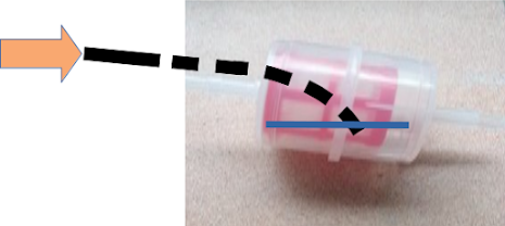
Modify one fuel filter to become a water mist collector and bubbler, by inserting the plastic fuel pipe into it (this is the most difficult part to get right). The fuel pipe usually comes in coils and has a natural curve, advantage can be take of the curve to position the tube inside the filter as shown below.
Modify the Jubilee clip by drilling a 4mm hole in the plain part of the band (this is used to secure the straight brass fitting in place.
Drill a 4mm hole in the side of the exhaust pipe towards the end of the exhaust (after any catalytic converter etc.) so it is collecting cooler exhaust gas but it is still feeling gas pressure from the hole.
Insert the straight brass fitting into the hole in the exhaust pipe and secure the fitting in place with exhaust jointing compound and the modified jubilee clip.
Attach a minimum of 1.6m of silicone hose to the straight fitting.
Connect the hose to the modified fuel filter (to the plastic fuel pipe end).
Add 150mm of hose to the outlet of the modified filter and then connect the second fuel filter to the other end of the 150mm length of hose.
Find locations to secure these parts with the filter ending up close to the engine inlet but not so close that they would melt. Fix in place with suitable clips and ties.
Find a location on the engine to introduce the gas. Just before the turbo on a turbo-diesel engine, just before the throttle butterfly if fuel injected (or carburettor) on a petrol engine. Note that on some engines it might be more practical to introduce the mist into the engine breather pipe.
Drill a hole to accept the brass 90 degree elbow (take care not to contaminate the engine with drillings or other dirt etc.).
Cut a length of silicone hose to connect the seconds standard fuel filter to the brass 90 degree elbow ensuring that it has sufficient length to allow of the relative movement of the engine to the location where the filter is secured to avoid and strain or entrapment.
Connect the hose to the second standard filter and the brass 90 degree elbow.
Insert the brass 90 degree elbow into the inlet and secure it with the high temperature silicone adhesive and clips/ties.
Pictures
In Line Diesel Fuel Filter
Note that the inner filter membrane must be plastic (not paper), and the filter core must be close to the outer wall of the filter body (second picture) to allow for the first plastic fuel pipe to deflect inside (to collect condensed water and also to create cool droplets), the second unmodified filter collects the droplets on the filter membrane which then converts it into fine mist for the engine.
Cut off the 6mm filter barb from the filter and insert the plastic fuel pipe into the filter inside the 8mm barb filter tube (the so that it nearly touches the filter membrane but so there is a gap to allow the exhaust gasses and liquid in). The 8mm barb may need to be heated (or even carefully drilled) to enable the plastic fuel pipe to be inserted. It must be a tight fit to stop it coming apart in use. (it is possible to use a larger piece of silicone hose and hose clips to ensure this pipe is secure with no leaks).
Note - The blue line indicates the approximate condensed water level when in operation.
Filter orientation when installed in the vehicle (side view)
Generic Schematic


